Reluctance Motor Types Overview and detailed Function
Synchronous Reluctance Motor and Switched Reluctance Motor
Reluctance Motor Types
Video about Reluctance Motors
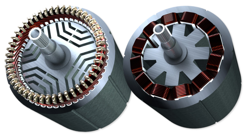
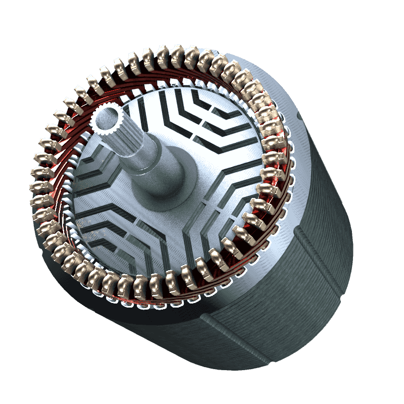
Synchronous Reluctance Motor
Switched Reluctance Motor
The switched reluctance motor (SRM) is also called SR-motor. The stator and the rotor of the switched reluctance motor consist of salient poles. The stator has a concentrated winding, which means that each tooth carries one winding. The number of stator poles and rotor poles must be different. As a rule, the number of poles in the stator is greater than that of the rotor. A typical combination is 6/4, i.e. 6 stator poles and 4 rotor poles. Since the rotor consists of only one laminated core, the SR motor is particularly good for very high speeds. The production of the switched reluctance motor is relatively simple, since windings can be pre-wound and only have to be pushed onto the teeth of the stator. The SR-motor has a higher torque ripple, which makes the motor louder than, for example, a synchronous reluctance motor. The torque ripple comes from the higher phase currents that the motor requires. The inverter or power electronics for switched reluctance motors is more expensive than for a synchronous reluctance motor, for example, because of the high phase currents. The resolution of the position sensor, on the other hand, can be low, allowing a less expensive sensor to be used.
