Losses in Electric Motors
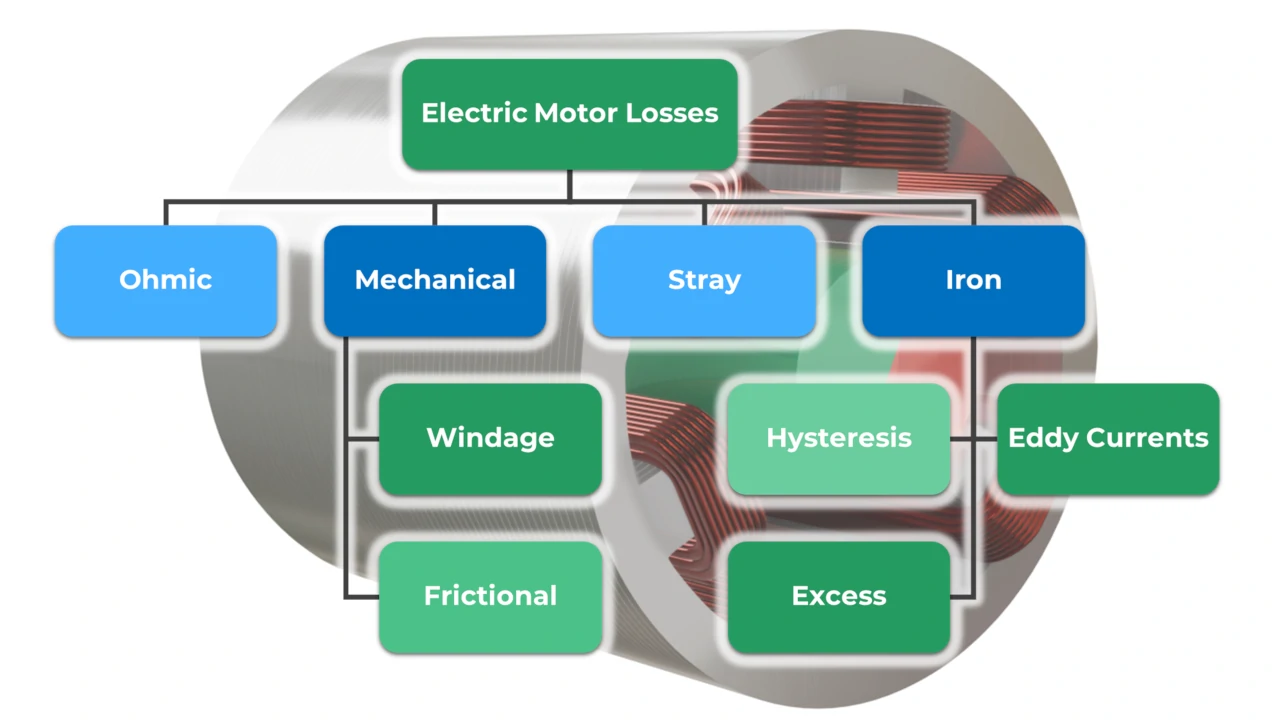
As seen here in the diagram, electric motor losses can be divided into ohmic losses, iron losses, stray losses, and mechanical losses. Ohmic losses are also called copper losses and iron losses, often also core losses. Electric motor losses occur in the stator laminations, rotor laminations and windings, and also in the permanent magnets. The lower the losses in the electric motor, the higher its efficiency, of course, more details about this in teh following video.
Video about Electric Motor Losses
Ohmic Losses
Ohmic losses occur primarily in the windings of the stator and are dependent on the resistance and the current. The ohmic losses can be divided into frequency dependent and frequency independent. The frequency independent losses depend on the dimensions, i.e. the length and the cross-sectional area of the wire, as well as the material, for example copper. A big increase of the motor temperature also increases the resistance and therefore also the losses. You should always make sure that the electric motor is well cooled, otherwise the temperature of the windings will rise quickly. The frequency dependent ohmic losses increase with increasing frequency, due to the skin effect. The skin effect reduces the area through which current can flow. To reduce this effect, wires with a large diameter are divided into several separate wires. However, dividing them into too many wires also increases the resistance due to the proximity effect. So it is not easy to find the best number of parallel wires. Induction motors also have high ohmic losses in the rotor, so the rotor gets hot quickly. It is very difficult to remove the heat from the rotor, so Tesla uses liquid cooling of the shaft in the induction motors.
Iron Losses
Iron losses can be divided into hysteresis losses, eddy current losses and additional losses. Iron losses are given per weight and depend on the frequency and the maximum flux density. This means that the faster the motor rotates, the higher the iron losses. And the smaller the electric motor is designed, the less space is left for the magnetic flux and the higher the flux density becomes. The proportionality constants C depend on the material and its manufacturing. Iron losses occur mostly in the stator and rotor, but eddy current losses can also occur in permanent magnets. Losses in magnets are usually small, but critical because magnets usually do not have good temperature resistance.
Hysteresis Losses
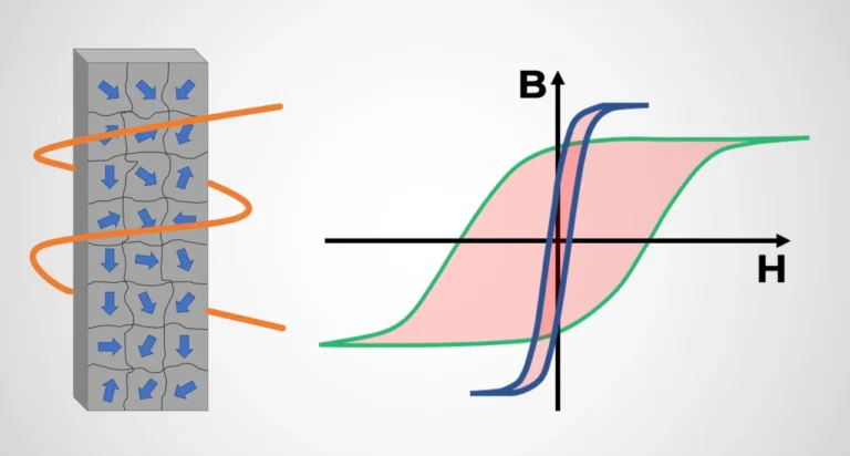
Magnetic materials are divided into many small domains, each with a different magnetic orientation. When the magnetic orientation of the domains changes, losses occur. These remagnetization losses are called hysteresis losses because the material passes through hysteresis during magnetization. The losses depend on the area of hysteresis the material passes through during remagnetization. To keep the losses low, soft magnetic materials such as electrical sheets with a small hysteresis curve are used.
Eddy Current Losses
Eddy currents occur when the magnetic flux in the stator changes. The eddy currents generate losses in the stator and heat it up. To reduce the losses, the stator is divided into separate laminations that are insulated from each other. This significantly reduces the eddy current losses. The thinner the sheets are made, the lower the eddy current losses in the sheet.
Additional Losses
As mentioned above, magnetic materials consist of areas separated by walls. A change in the magnetic field can cause a displacement of the walls, which leads to losses. These losses are called additional losses or excess losses.

Stray losses
Mechanical Losses
Mechanical losses can be divided into friction losses and ventilation losses. Frictional losses depend on the speed and occur, for example, in the bearings. To keep frictional losses as low as possible, the bearings should always be properly lubricated. The bearings must therefore not become too hot, otherwise the lubricant will dissipate. Friction losses also occur in the brushes of separately excited synchronous motors and commutators of DC motors. Ventilation losses occur in electric motors with non-round rotors and also depend on the speed. For example, sr-motors or separately excited synchronous motors have rotors that are not round. By casting the stator and banding the rotor, the ventilation can be reduced. If cast with the right material, this can also improve heat dissipation. Ventilation in electric motors can also be used to move heat out of the center of the electric motor. This distributes the heat better in the electric motor and reduces hotspots.
Power Loss Flow Chart
The visualization of the conversion of the power of electric motors and generators is illustrated with the help of the power flow diagram. In electrical motors, the diagram shows how much electrical input power is supplied and how much mechanical output power remains after the power losses have been dissipated. In a generator, the flow of power dissipation reverses. This means that if you have too much friction in the bearings, there is less power left to convert into electrical power.
