DC Motor

Design DC Motor
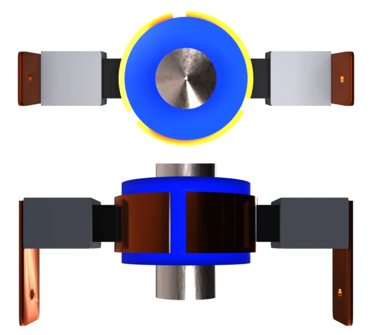
Like any electric motor, the DC motor consists of a rotor and a stator. Unlike AC motors, the non-rotating stator of the DC motor consists of permanent magnets. The permanent magnets are attached to a cylindrical shroud made of sheet metal. The rotating rotor consists of individual thin electrical sheets. The rotor is wound with the windings made of copper wire. The individual windings are connected to the commutator. Two brushes for the plus and minus pole loop on the rotating commutator. The brushes can be made of carbon pins or metal, for example. To improve the contact, the carbon pins are pressed onto the commutator by small springs. The brushes are connected to the plus and minus poles for the DC voltage. Unlike an AC motor, which usually has three terminals for the power supply, the DC motor has only two terminals for a DC voltage.
Function DC Motor
Like any electric motor, the DC motor requires a changing magnetic field, which changes depending on the position. The magnetic field is generated by a current flow in the windings. In order for the magnetic field to change depending on the position, the direction of the current flow in the windings must change. This is exactly what the so-called commutator is needed for, which changes the polarity of the voltage applied to the windings. So the commutator ensures that either a positive voltage or a negative voltage is applied to windings. Therefore, the direction of current flow in the winding also changes and so does the magnetic field. The commutator can therefore be regarded as a mechanical inverter which turns the DC current in the motor into an AC current for the windings. This is why the commutator is also called a mechanical current inverter.
DC Motor Types
There are three different types of DC motors:
- self-excited DC motor
- separately excited DC motor
- permanent magnet DC motor
The permanent magnet DC motor is the most popular due to its simple design. The separately excited DC motor and self-excited DC motor do not have permanent magnets in the stator; instead, these DC motors use electromagnets in the stator. For self-excited DC motors, the voltage for the electromagnet is used directly from the DC voltage. Instead, separately excited DC motors use an additional voltage that can be set independently of the DC voltage of the DC motor. The direct counterpart to DC motors are brushless DC motors, or BLDC motors. As the name implies, BLDC motors do not have brushes, so they do not have a commutator. Brushless motors belong to the AC motors. Ironless or slotless DC motors have no slots in the rotor, i.e. no teeth around which windings are wound. The windings are therefore wound around air, so to speak. This is why the term “air gap winding” is used.
Control DC Motor
The direction of rotation can be easily set via the polarity at the two terminals of the DC motor. So for example +12V for clockwise rotation and ‑12V for counterclockwise rotation. The exact supply voltage and direction of rotation should be taken from the data sheet of the manufacturer of the DC motor. The speed can be changed via the voltage of the DC motor. However, in order to control the speed correctly, a sensor or encoder is needed to detect the speed. There are also special methods to calculate the speed from the motor current. A PI controller can be used as a regulator, which adjusts the voltage depending on the deviation between the setpoint and actual speed. The voltage level adjusted in this way changes the DC current flowing through the motor. In this way, the speed of the DC motor is controlled to the set speed.

DC Motors Applications
DC motors are mostly used for simple actuators. A large area of application for actuators with DC motors is the automotive industry. There, DC motors are used for flaps and valves. Also in modelling, many DC motors are used for servo drives to steer model airplanes and for remote-controlled cars and boats.